
Instructions for Customizing a Monogrammed iPhone 5 Case and printing at Shapeways
This instruction set was written for Sketchup Version 8.0.16846, if you see any corrections or changes for a later version, please send them to me at Jeff@WB3B.com. All I ask in return for using my instructions and the initial design it that you send me a picture of your finished product to Jeff@WB3B.com -- Have fun!
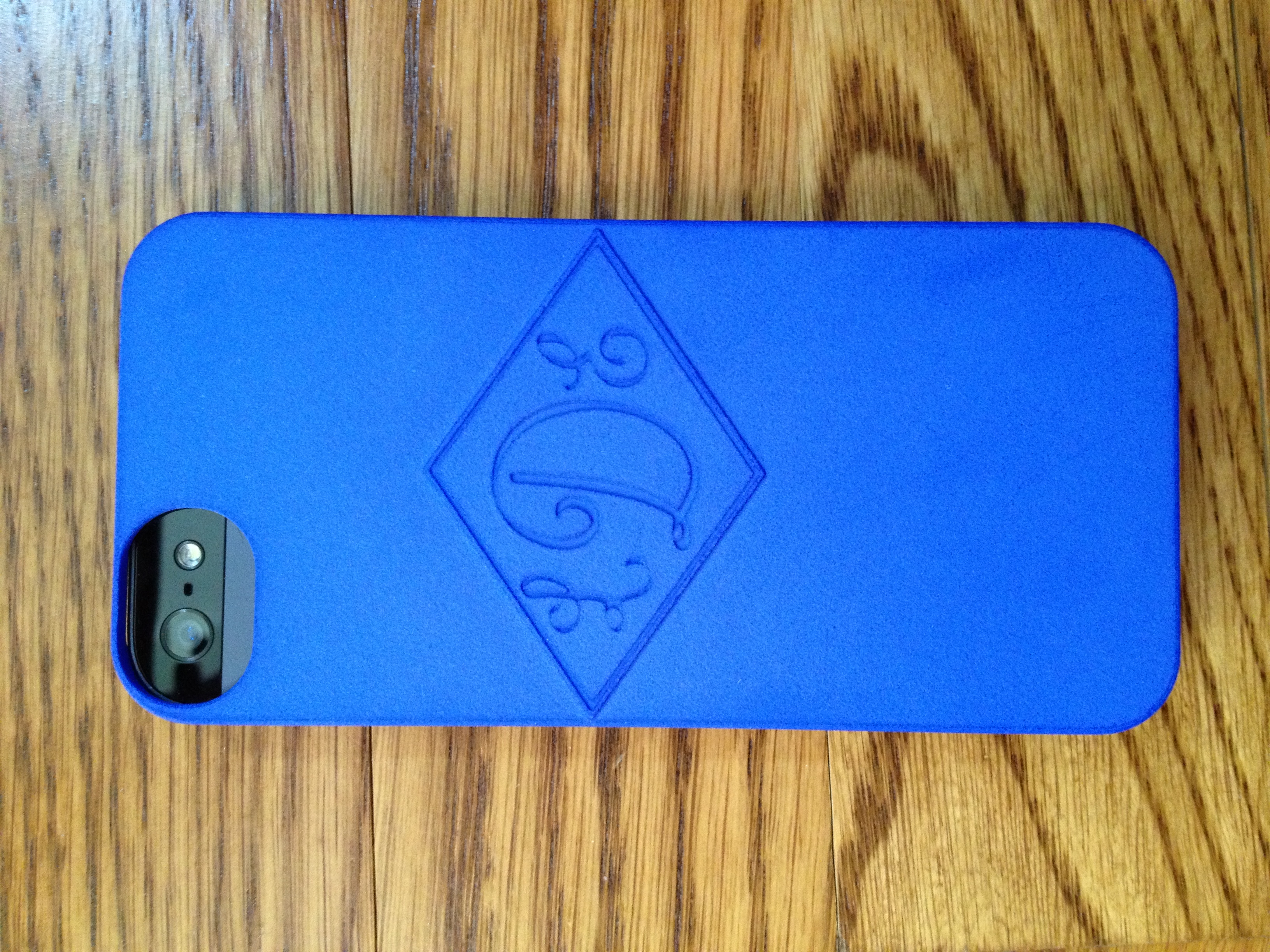
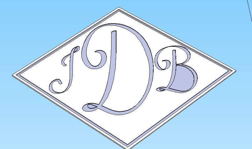
Here's a picture of the finished product I did for my daughter, you will be starting with this design -- Hi Res Version
1. Open the .skp with Laura’s initials in Google Sketchup, Click here to get the file. You can download Sketchup at http://www.sketchup.com/intl/en/ for free if you don’t have a recent version already installed
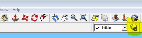
2. Show the layers pallet (If this does not show in your tool bar goto to EDIT(or VIEW depending on version) > TOOLBARS > and check LAYERS)
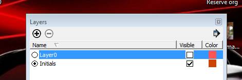
3. Make Initials layer current and Layer0 Invisible
4. Press O (Oh) on the keyboard to enter Orbit mode and drag with left mouse to view. Press Z then drag to zoom or H then drag to pan (remember these you will use them a lot)
5. Zoom in and arrange so that letters are near full screen and slightly oblique so you can see the sides where they are indented
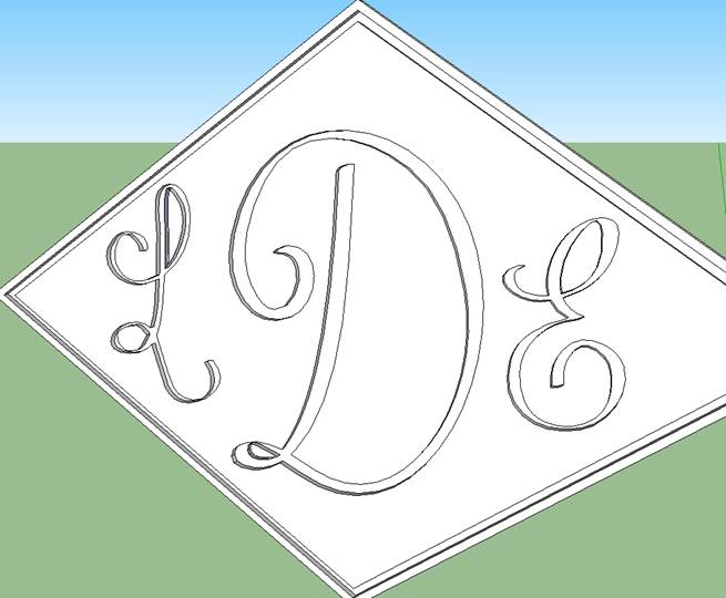
6. Press the Space bar to enter select mode, Click on an open area of the screen to deselect everything then click somewhere on the plane around the letters (it will become filled with dots) and delete the front plane with the delete key.
7. Click again on the plane around the letters and delete, this time you will delete the back plane.
8. Just in case -- anything can be undone with Ctrl-Z, multiple Ctrl-Z will undo multiple things
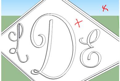
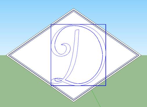
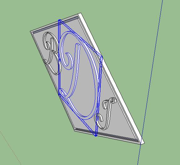
9. Click on portions of the letters and central plane to delete all of the central graphics. You can double and triple click to select adjacent graphics all at once, but be careful not to delete the bounding box around the letters highlighted below.
10. You should now just have an empty frame – now we need to rebuild the front and back planes
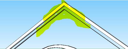
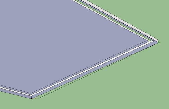
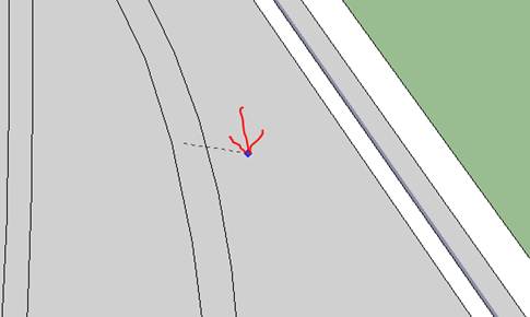
11. Use O, H and Z to position so you can clearly see the inside ribbon at the top of the frame. Start drawing a line at this point by picking the line tool (press L) and clicking on this point. Move the mouse down to begin drawing a line.
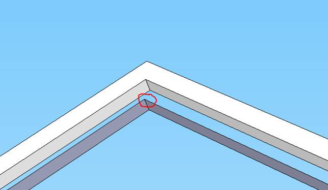
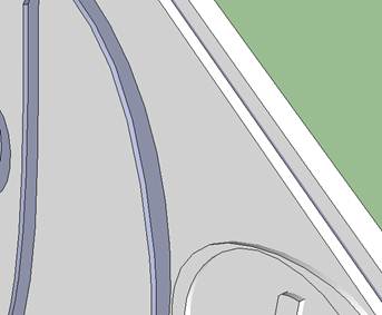
12. Select O and Z, H as necessary to view the bottom of the frame, press L to get back to the line tool and click on the bottom of the ribbon at the point shown, this should cause the front plane to reappear.
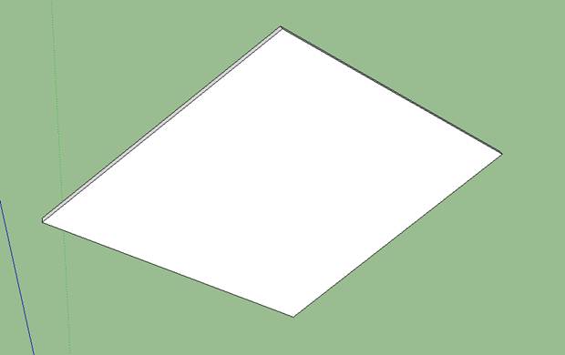
13. Now click on the line you just drew and delete it. The plane should stay. (anytime you complete a polygon in a plane, the surface will be drawn)
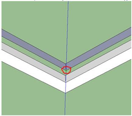
14. Now use O,H & Z to look at the back of the frame and draw another diagonal (press L for the line tool) to the far corners, or just retrace one of the back lines to reform the back plane. Delete the diagonal afterward if you use one
15. You should be back to an empty frame now The back should be flat and the front will have edges – I guess I could have given you this to start with?
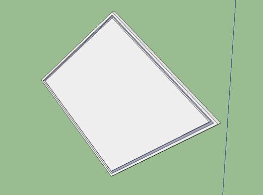
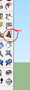
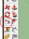
16. Now we add back the letters you want, position the frame so the front is toward you – (CAMERA > STANDARD VIEWS > FRONT is a good shortcut) Select the Text tool from the toolbar at left. (If this does not show in your tool bar goto to EDIT > TOOLBARS > and check LARGE TOOL SET)
17. Start with the large middle letter by typing it in the dialog box and make it 15 to 20 in Height and 1 Extruded. Select a font you like, but don’t use a real delicate one with thin walls (you will see what I mean when you place it)
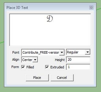
18. Click place and position it in the center of the frame. If it is too large or small hit escape or Ctrl Z and repeat with a different height.
You can also use the Scale tool Press S
or select 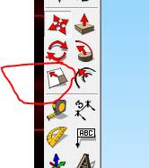 to change or
aspect of the letter, but be sure to use one of the “center” handles so you
don’t change the depth of the letter or the position of the back of the letter.
to change or
aspect of the letter, but be sure to use one of the “center” handles so you
don’t change the depth of the letter or the position of the back of the letter.
19. Add the two smaller letters the same way, but use a height of roughly 10 and keep extrusion at 1.
20. If you need to move the letter, press the space bar then click on the letter to select it, press the M to enter move mode and drag the letter where you want it. Use O afterward to be sure it is still on the plane of the frame
21. Now we need to move the letters into the frame and erase the front planes of the letters.
22. Save your file at this point, as the next step is easy to mess up and you may want to get back to the current state by reloading the file
23. Hit space bar and select a letter, Hold the shift key and select/add the other two letters
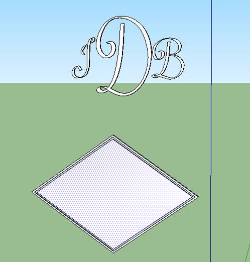
24. Press M to begin a move – Click somewhere on the blue highlight, move the letters up above the frame circle around until you see the text “on the blue axis” near your cursor, you can help force it on the blue axis by pressing the up arrow. Type in 40 and hit Enter to move the letter up 40 units – this will get them out of the frame area.
25. Hit the space bar and select all of the letters again (you can use the shift to click and add or drag a box around all three)
26. Right click on a highlighted portion and select explode
27. We need to move the letters back ½ unit on the green axis, so position your view (O,Z H) to see them in an oblique view or select CAMERA > STANDARD VIEWS > ISO
28. While the components of the letter are still highlighted, hit M to enter move mode, click on a blue portion of the letter move the mouse toward the back of the letters, move it around until you see the text “on green axis” appear, (holding down the left arrow may help get you on the green axis – right arrow is red axis and up arrow is blue axis for later info ) type in .5 and hit the enter then hit the space bar. You should have just moved the letters back ½ units of measure.
29. Now we need to move them back down into the frame.
30. Select the letters again, (triple Click, use shift and click to add or drag a box)
31. Press M and move the letters down “on the Blue axis” 40 units (See step 24 above for similar detail just move down instead of up)
32. The letters are now ½ in the plane and ½ out of the plane.
33. Press the space bar, click outside of the images to be sure nothing is selected, then press the P key or select the push tool
34. Click on the face of one of the letters then click on the plane, this will move the face of the letter to the pane and it should open up the letter as shown below.
35. Repeat for remaining 2 letters
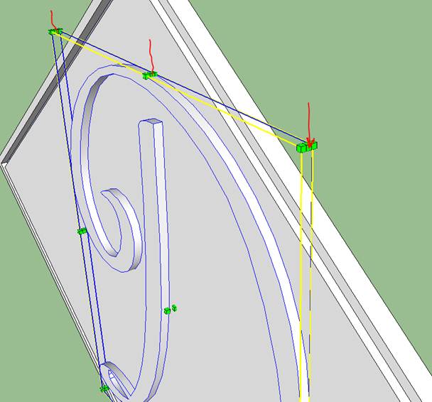
36. Almost there -- if there are any closed areas in your letters like the bottom of the B and loops in the B, D and J below, you will need to build the plane back up for them.
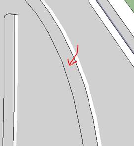
37. The easiest way is to draw a line from one point of the top surface of the hole to another non-adjacent top point. Use O,Z & H to get a good view as below

38. Use L to draw a line between these points, the face should close as below. Then hit the space, click on the line you just drew to select and delete it. The face will remain.

39. Repeat for other similar area and save your project. The areas may continue to show a different color, but they are correct.
40. Go back to the Layers Dialog (step 2) and make Layer0 visible. Use O, Z and H to view your project.
41. Save your file then do a FILE > EXPORT > 3D Model and save it again in the .dae format
You are done with the design, all you need to do now is convert it to the proper format and close any internal “watertight / solid” issues then send it to www.shapeways.com or some other printer to be produced.
42. You need to run the model thru two more programs to get it into a .stl file and to ensure that the mode it “watertight” (doesn’t have any holes in the model keeping it from being solid.
43.
You will need the programs below (free downloads). Download and install the
following 2 software programs now.
MeshLab (
I used version 1.3.2)
This
is a software program which can open and convert several file types.
Netfabb ( I used version 4.9.4)
This is a free program which can edit stl's. It can open a stl and shows basic failures on a model. It also has the basic features to edit a stl like analyze, scaling, measuring and repair.

Download (scroll down, information is not needed to get access to the download.)
44. Open Meshlab
45. Do a FILE > IMPORT MESH and open the .dae file you saved above
46. Accept Full Scene
47. Left Click and drag to view model
48. Select FILE > Export Mesh as…”
49. Save file as a .stl format
50. Open NetFabb
51. PROJECT > OPEN and open the .stl file above
52. You will use the analyze and heal features to fix model – It had consistently fixed mine with the default settings

53. Click the Analyze > Standard Buttons and see any problems highlighted on the right
54. Click the Heal Button, select Automatic Repair and Apply repair in lower Right Corner
55. Accept to delete old parts
56. Select from Menu PART > EXPORT PART > as .stl and save repaired part
57. Create a free account at www.Shapeways.com or find an alternative 3D printer
58. Upload the .stl file from step 56 to Shapeways, indicate measurements are in Millimeters (mm)

59. You will receive an email when your model is accepted and ready to be printed.
60. Go back to the site and go to the “My Models” sections

61. Click on the name of your model - Select one of the Strong and flexible materials - any color and add it to your cart.
62. Complete the order, your print should cost around $24 plus shipping
Please let me know how this works out for you and don’t forget to send me an image of your finished product. If you need help along the way, please describe your issue and send a copy of your .skp file to Jeff@WB3B.com.

9546 Hampton Reserve Dr
Brentwood, TN 37027
(615) 371 1825 h
(615) 934 1291 c
(615) 345-0541 f